
![]()
Terminals for connecting MultiTransmitter Fibra to the hub:
+24 V — 24 V⎓ power supply terminal.
А, B — signal terminals.
GND — power ground terminal.
Terminals for connecting wired devices to MultiTransmitter Fibra:
Z1–Z18 — inputs for connecting wired devices.
+12 V — power supply output for wired devices, voltage 10.5–15 V⎓, up to 1 A in total for all power supply outputs.
+12V2 — power supply output for fire detectors, voltage 10.5–15 V⎓, up to 0.4 A in total for all power supply outputs.
COM — common input for connecting power supply circuits and signal contacts of wired devices.
Operating principle
MultiTransmitter Fibra is designed to integrate third-party wired devices into an Ajax security system. The integration module receives information about alarms, malfunctions, and events from devices through a wired connection. After that, it sends the event to Hub Hybrid using the Fibra data transfer wired protocol. And Hub Hybrid sends messages to users and the security company CMS (central monitoring station).
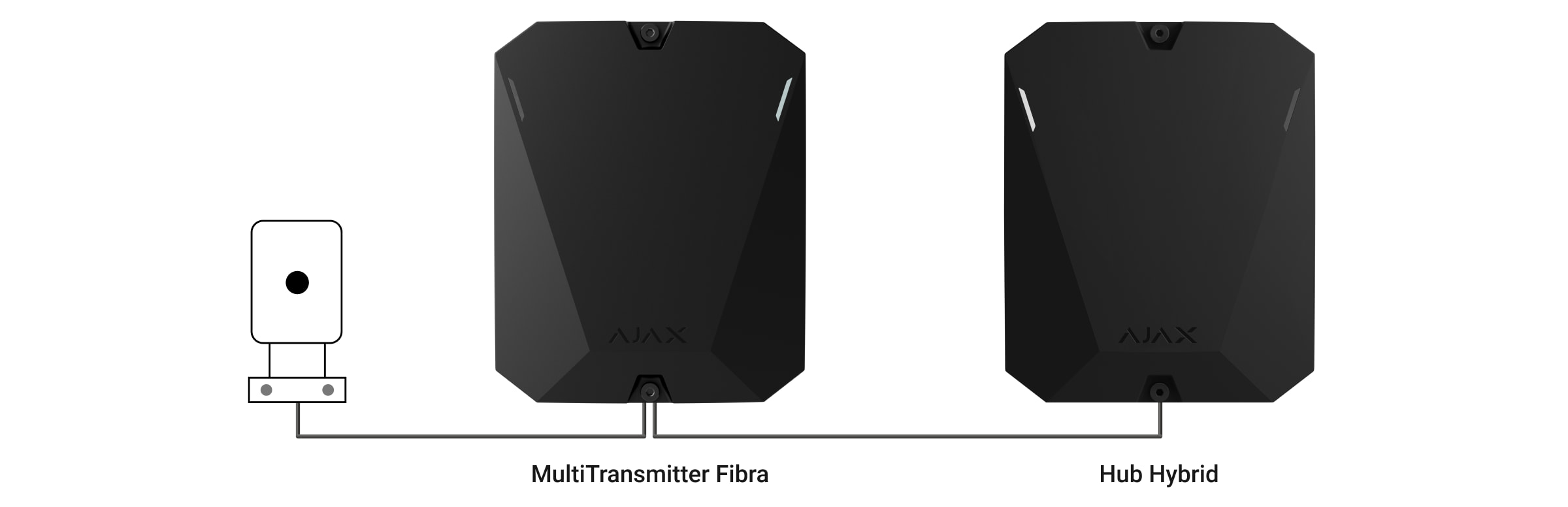
MultiTransmitter Fibra is used to integrate alarm and auxiliary request alert buttons, indoor and outdoor motion detectors. As well as detectors that track opening, vibration, glass breaking, fire, gas and water leakage, etc.
Connecting MultiTransmitter Fibra to the hub
- Remove the MultiTransmitter Fibra casing lid by unscrewing the bottom and top screws with the bundled hex wrench.
- Remove the MultiTransmitter Fibra board from the holders by pulling them to the sides.
- Prepare cable openings in advance by carefully breaking out the perforated parts of the casing.

- Fasten the casing to a vertical surface at the chosen installation location using the bundled screws. When attaching, use all fixing points on the casing. One of them is in the perforated part above the tamper — it is required for tamper triggering in case of any attempt to detach MultiTransmitter Fibra casing.
- Disconnect the external power and the hub backup battery.
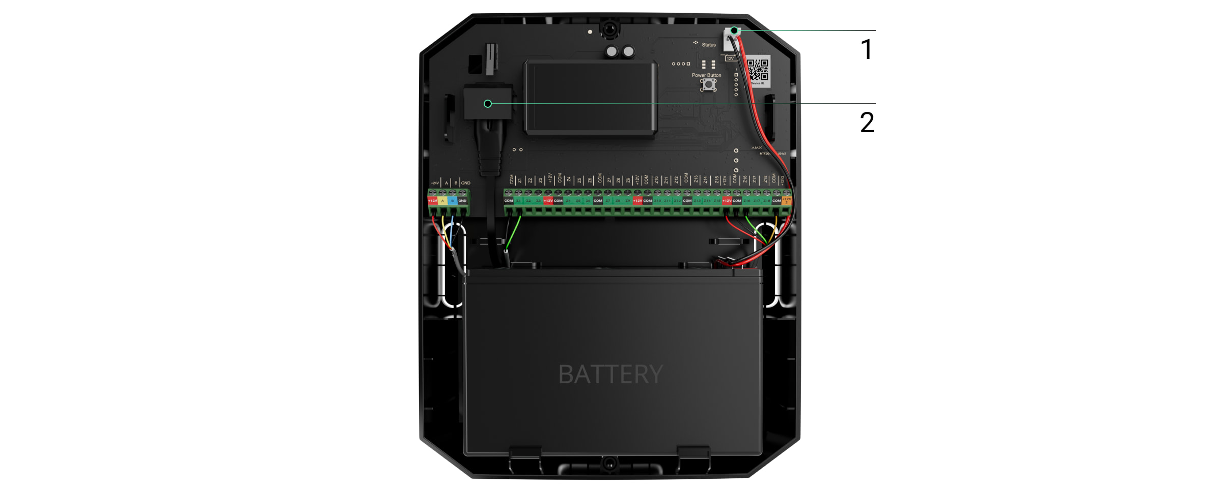
1 — Backup battery.
2 — External power.
To comply with the INCERT requirements, use the Screw terminal block Adapter to connect the external power supply. Read more.
- Pull the cable into the hub. Connect the wires to the hub line.
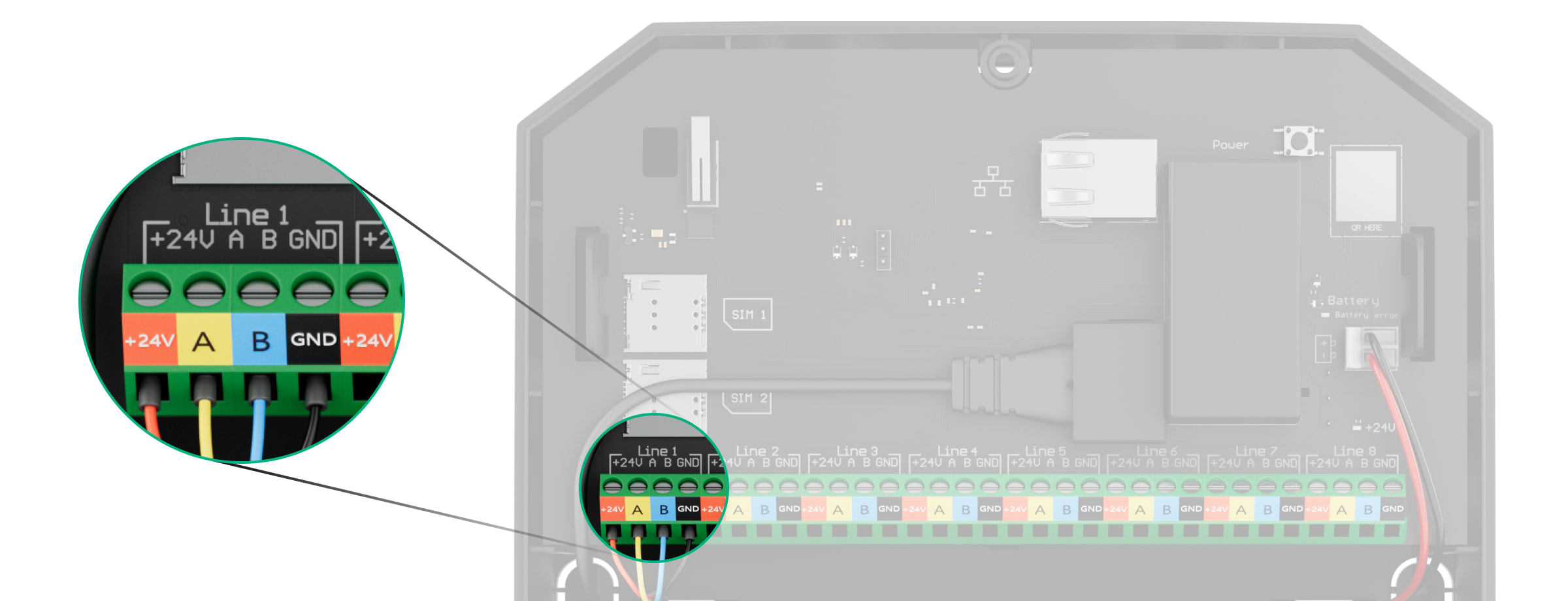
+24V — power supply terminal of 24 V⎓.
А, B — signal terminals.
GND — power ground terminal. - Pull the cable from the hub into the casing of the integration module through the holes made.
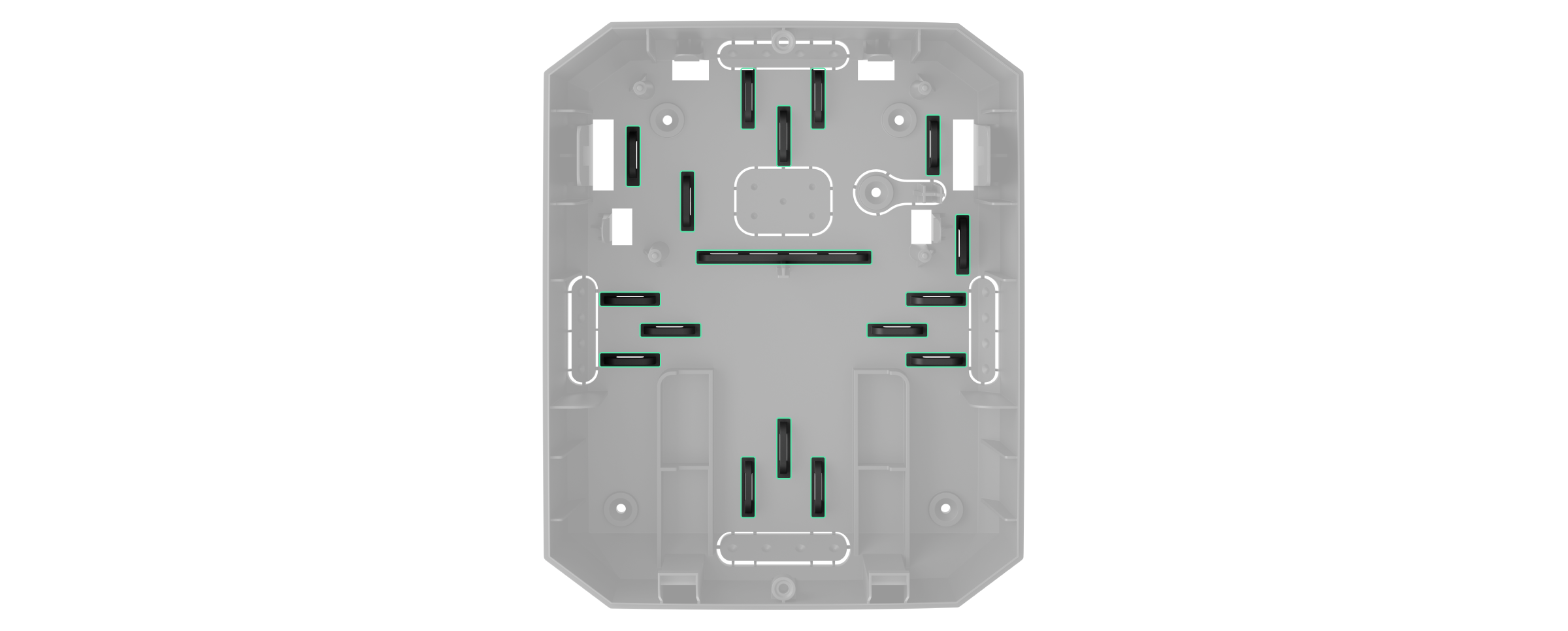
- Install the MultiTransmitter Fibra board into the casing on special holders.
- If the integration module is not the last in the connection line, prepare a second cable in advance. The ends of the wires of the first and second cables that will be inserted into the terminals of the device should be tinned and soldered together or crimped with a special sleeve.
- Connect the wires to the terminals according to the diagram below. Follow the polarity and connection order of the wires. Securely fasten the conductors to the terminals.
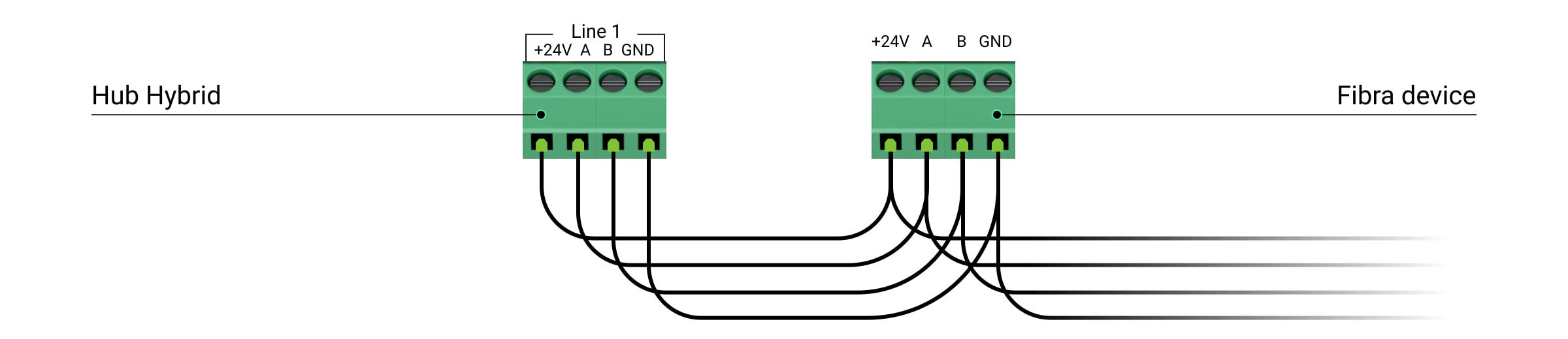
+24V — power supply terminal of 24 V⎓.
А, B — signal terminals.
GND — power ground terminal. - When using Beam (Radial) topology: if the integration module is the last in a line, install a terminating resistor by connecting it to the signal terminals of the device. For the Ring topology terminating resistor is not needed.
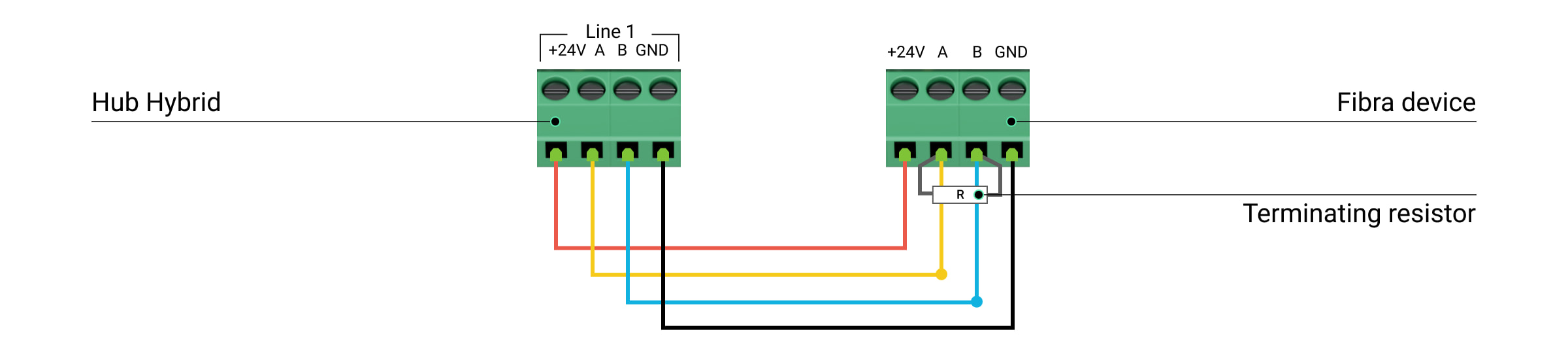
If possible, we recommend connecting devices using the Ring topology (hub—device—hub). This improves the antisabotage protection of the system.
- Secure the cables with cable ties using special mounts in the casing.
- Install a 12V⎓ backup battery on the special holders in a casing. Please note that MultiTransmitter Fibra cannot be connected to third-party power supply units.
Use 12 V⎓ batteries with a capacity of 4 or 7 A∙h. For such batteries, special holders in the casing are designed. You can also use similar batteries of a different capacity, of the matching size, and with a charging time of no more than 30 hours. The maximum dimensions of the battery to be installed in the casing are 150 × 65 × 94 mm, and the weight is 5 kg.
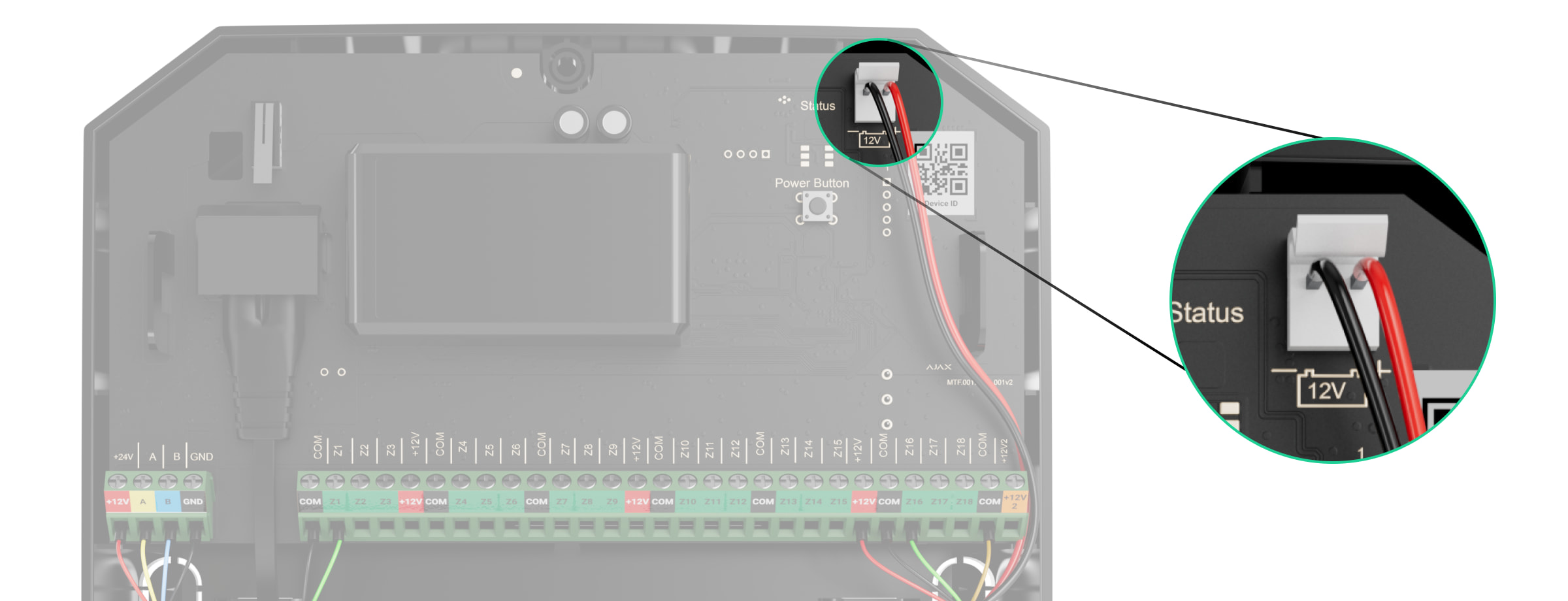
- Connect the backup battery with the bundled cable to the board terminals according to the wiring diagram below. Follow the polarity and connection order of the wires. Securely fasten the conductors to the terminals.
- Connect the external 100-240 V~ power supply to the integration module.
- Connect the backup battery and external power supply to the hub. Turn on the hub.
- Add an integration module to the system.
- Run a Fibra signal strength test. The recommended signal strength is two or three bars. If the signal strength is one or zero bars, check the connection’s correctness and the cable’s integrity.
- Install the lid on the integration module casing. Secure it with screws at the bottom and top of the lid using the bundled hex wrench.
Connecting wired devices to MultiTransmitter Fibra
- Remove the MultiTransmitter Fibra casing lid by unscrewing the bottom and top screws with the bundled hex wrench.
- Turn off MultiTransmitter Fibra by holding down the on/off button.
- Disconnect 100-240 V~ external power and MultiTransmitter Fibra backup battery.
- Select the MultiTransmitter Fibra zone to which you want to connect a device.
- Pull the third-party device cable into the integration module casing.
- Connect the device to MultiTransmitter Fibra, securely fixing the wires in the terminals. The wiring diagram can be found in the user manual provided by the manufacturer of the wired device.
Read the manufacturer’s instructions before connecting the device to MultiTransmitter Fibra.
- Secure the cable with cable ties using special mounts inside the casing.
- Connect 100-240 V~ external power and backup battery to MultiTransmitter Fibra.
- Add device to the system.
- Test the operation of the connected wired device.
Adding to the system
MultiTransmitter Fibra is compatible only with Hub Hybrid (2G) and Hub Hybrid (4G). control panels. Only verified partners can add and configure Fibra devices in Ajax PRO apps.
Before adding MultiTransmitter Fibra
- Install the Ajax app. Create an account if you don’t already have one.
- Add a hub compatible with the integration module to the app, set the necessary settings, and create at least one virtual room.
- Make sure that the hub is on and has Internet access via Ethernet and/or cellular network. You can do this in the Ajax app or by looking at the LED on the hub board. It should light up white or green.
- Make sure the hub is disarmed and not updated by looking at its state in the Ajax app.
- Make sure the MultiTransmitter Fibra integration module is physically connected to the hub.
How to add MultiTransmitter Fibra
To add an integration module manually
- Open the Ajax PRO app. Select the hub you want to pair MultiTransmitter Fibra with.
- Go to the Devices
 tab and click Add device.
 - Specify a name for the integration module.
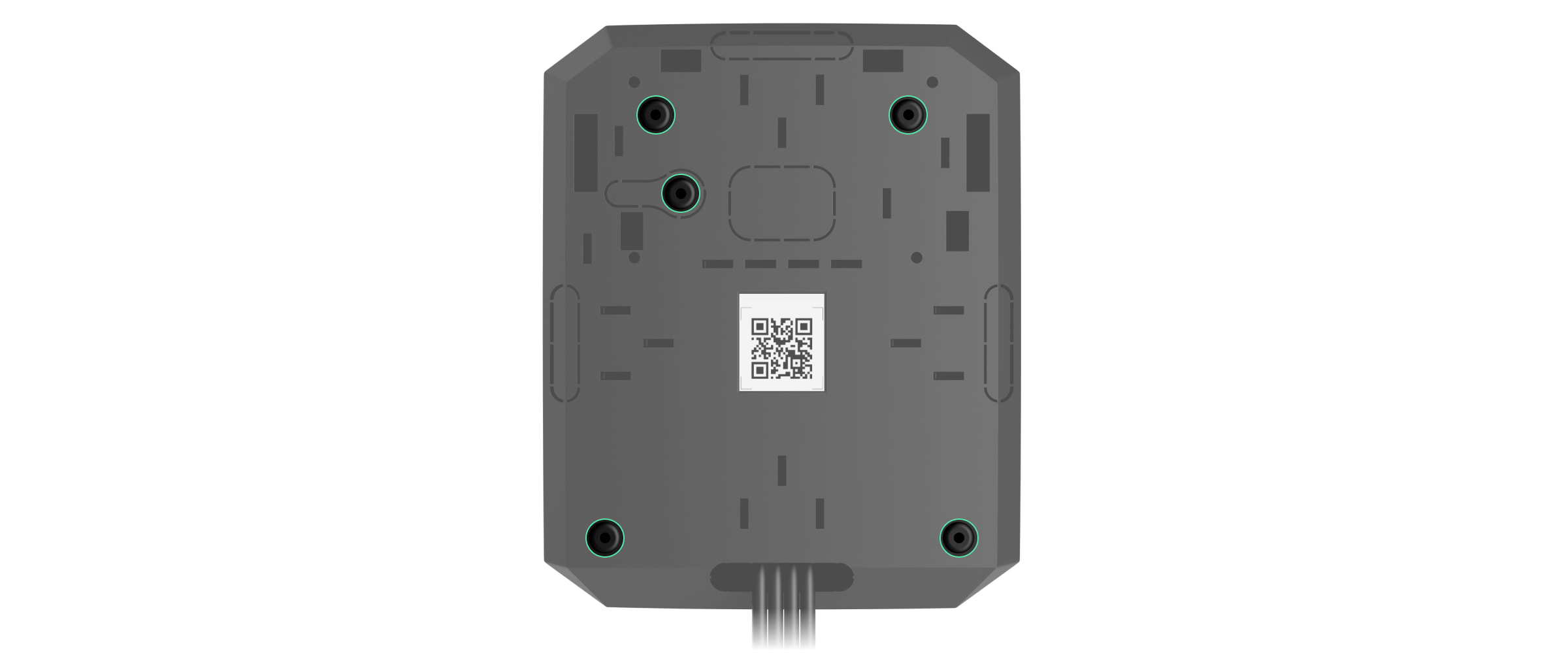
- Scan or enter the QR code manually. The QR code is located on the integration module board, on the back of the casing, and on the package.
- Select a virtual room and a security group if the group mode is enabled.
- Press Add.
- Turn on the integration module by holding the on/off button.
For the integration module to be added automatically
- Open the Ajax PRO app. Select the hub to which you want to add physically connected devices.
- Go to the Devices tab and click Add Device.
- Select Add All Fibra Devices. The hub will scan the Fibra lines. After scanning, all devices physically connected to the hub will be shown on the Devices tab. The order of the devices will depend on which line they are connected to.
- In the list of available for adding devices, click on the one you need. After pressing, the LED indicator of this device will start flashing. This way, you’ll know exactly which device you’re adding, how to name it correctly, and which room and group it should be connected to.
- To add a device, specify a name, room, and security group if the group mode is enabled. Press Add. If the device was successfully added to the hub, it disappears from the list of devices available for adding and displays on the Devices tab in the app.
MultiTransmitter Fibra works with one hub only. After connecting to a new hub, the integration module stops exchanging commands with the old one. After adding to the new hub MultiTransmitter Fibra is not removed from the list of the old hub. You should do it manually in Ajax apps.
Opmerkingen
0 opmerkingen
U moet u aanmelden om een opmerking te plaatsen.